Navien wall hung boiler question

Users who are viewing this thread

Cadobe

Member
Messages
35
Reaction score
1
Points
8
Location
Seattle
The pumping head of the heat exchanger in the Navien is much higher than a cast iron boiler- you may or may not be able to push enough flow through that HX to support what the radiation needs. If you have the software or are really good with a paper & pencil it's possible to figure out what's needed and what's possible and spec the pump, but if you're not sure it's easier to just plumb it primary/secondary with a hydraulic separator (such as the pre-engineered manifold).

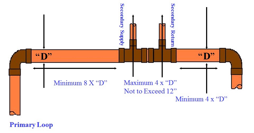
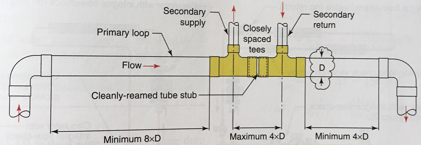
You can make your own hydraulic separator out of fittings using closely spaced tees, but the tees have to be spaced very closely to achieve adequate separation between the primary (boiler loop) and secondary (radiation loop) flows.

attachment.php


How much radiation, is there on this system, and which model Navien? It's pretty common to see these condensing boilers hooked up to systems that don't have enough radiation to run the boiler in condensing mode without short-cycling. See this bit o' bloggery for the napkin math on that.

The secondary supply/return can have the same diameter as primary loop pipe? The image is clearly telling that dimensions are different, but I just asking.
 

Dana

In the trades
Messages
7,889
Reaction score
509
Points
113
Location
01609
The secondary supply/return can have the same diameter as primary loop pipe? The image is clearly telling that dimensions are different, but I just asking.

The hydraulic separation is better if the pipe between the tees is considerably fatter than the primary or secondary loop plumbing. If building your own manifold the general rules of thumb are to keep the center-to-center difference between the tees no more than 4 diameters of the manifold pipe, and make the nearest ell least 8 manifold diameters from the nearest tee on the incoming side of the manifold, and at least 4 manifold diameters to the nearest ell on the outgoing side.

rzhxpftnz3h4.png


It's fine to use reducers at at those distances too. The point is to keep the turbulence and velocity to a minimum in that section of pipe.

Primary and secondary designations can be flipped relative to that drawing- hydrodynamics don't really care which one is called primary or secondary.
 

Cadobe

Member
Messages
35
Reaction score
1
Points
8
Location
Seattle
Got it. Thumbs up for you.

If the manual says so, then follow the manual, I always do. As a side note....just digging installs, I never saw one image install having/keeping the side dimensions required, which ....you remember about so called "contractors".

Even with commercial Navien manifold kit never saw extended to the required sizes.

My best regards Dana
 

Cadobe

Member
Messages
35
Reaction score
1
Points
8
Location
Seattle
Follow up.

Navien NCB installation manual on page 11, the schematic assembly shows that the first connector on the left hand side is for Space Heating Supply and second one is for Space Heating Return right?

Now, according to the Modern Hydronic Heating systems, we need to have for the "required" manifold on the supply side, a distance not less than 8*D and the return side a distance of minimum 4*D right?

Please see the image below, image taken from a Plumbing Shop showroom, located near me. The unit is a combi boiler NCB E series.

6.jpg


Am I missing something, or they do?
 

Dana

In the trades
Messages
7,889
Reaction score
509
Points
113
Location
01609
The flow direction in the photograph of the showroom model is flipped relative to this diagram.

rzhxpftnz3h4.png


It looks like they have a adequate 8xD+ on the inbound side, but cheated the 4xD+ on the outbound side of the flow by at least a couple diameters. That's not a showstopper, but it's not best practices.

Another subtlety is that there should be a straight section of pipe ahead of the air separator and expansion tank, with another straight section between the tank and the system/secondary pump (not in the picture.) It looks like they dropped in a pair of 45 degree ells to create an offset just ahead of the air separator. That particular model air separator isn't sensitive to turbulence so they can get away with it (it meets the manufacturer's spec) , but it's not clear what they did between the air separator and pump. It looks like it feeds right into another 45 ell. Ideally the expansion tank would be set up where it can behave as a shock-absorber, on a short straight run into the intake side of the pump, reducing the potential for impeller cavitation. If there are a couple of ells before the pump the turbulence and impedance reduces the ability of the expansion tank to suppress cavitation. On a section of 3/4" copper each 45 ell is the friction equivalent of a foot of straight pipe, and it's inducing turbulence at a point where turbulence is best minimized.

Again, not a show stopper- every body's a critic, right? ;)

They probably did all of those things simply to make the display a more compact, and I've seen worse that worked just fine.
 
Top
Hey, wait a minute.

This is awkward, but...

It looks like you're using an ad blocker. We get it, but (1) terrylove.com can't live without ads, and (2) ad blockers can cause issues with videos and comments. If you'd like to support the site, please allow ads.

If any particular ad is your REASON for blocking ads, please let us know. We might be able to do something about it. Thanks.
I've Disabled AdBlock    No Thanks