I had a Navien NCB240 installed about 1 year ago and I have always thought that the installers design for the closed loop side was a bit odd/wrong. He didn't use the Navien manifold accessory and instead built a simple loop with the supply at the top and return at the bottom with a recirculator pump on the return. Do any experienced people have comments on the supply/return loop he installed. The system works ok when the burner is firing but when it simply runs the re-circulation the internal sensor temp stays really steady and slowly cools down. A new issue I have had this year is the PSI dropping after a few days. I topped up the water in the loop to bring it up to 17psi with unheated water, it gets up to 28psi when the burner is on. I added psi to the expansion tank to match the 17psi, it has been working for a few days without issue but it has dropped suddenly to 1psi 3 times since we turned the system back on this year. I did just install a Tekmar 519 with infloor sensor and outdoor rest and set the curve to high mass as we have concrete floor heat with 5 loops in the basement - 800 sq ft.


You are using an out of date browser. It may not display this or other websites correctly.
You should upgrade or use an alternative browser.
You should upgrade or use an alternative browser.
Closed Loop design for Navien 240 NCB
- Thread starter yourefree
- Start date
-
- Tags
- navien 240
Users who are viewing this thread
Total: 2 (members: 0, guests: 2)
The sudden drops to 1 psi is an indication the system is losing water. It's possible that it is occasionally peaking at a 30 psi and sending a huge slug of water out of a 30psi pressure relief valve overflow plumbing, which would explain a sudden drop. Unless the slab is 3 stories or more above the Navien there's no reason to set it up for 17psi. A more typical cool/tepid system pressure for 1 & 2 story homes would be 12 psi which would give you some margin on the relief valve.
The expansion tank looks a bit on the small-ish side for a radiant system. Have you done the math on the total water volume and temperature swing.
As long as the flow is adequate and the difference in supply & return temperatures aren't outlandish it can be fine to pump direct or use a less-than-perfect hydraulic separator. The Navien-built manifold is just a pre-engineered closely-spaced tee type hydraulic separator. It's a little hard to figure out the plumbing configuration from the oblique angle pictures.
Sponsor
Paid Advertisement
Sorry for the poor pictures. I will try to take better ones. it is in a small space. I have 3/8" pex 769 total feet so only 4.06 gallons in that system. The only run is in the basement as we couldn't retrofit the rest of the old house. I will reduce some of the psi and see if it still works. I cannot detect any leaks - I have isolated the loop to test to water loss and it stayed constant. Maybe it is the expansion tank failing although I checked that and it wasn't full of water in the bottom and had 11 psi or so.The sudden drops to 1 psi is an indication the system is losing water. It's possible that it is occasionally peaking at a 30 psi and sending a huge slug of water out of a 30psi pressure relief valve overflow plumbing, which would explain a sudden drop. Unless the slab is 3 stories or more above the Navien there's no reason to set it up for 17psi. A more typical cool/tepid system pressure for 1 & 2 story homes would be 12 psi which would give you some margin on the relief valve.
The expansion tank looks a bit on the small-ish side for a radiant system. Have you done the math on the total water volume and temperature swing.
As long as the flow is adequate and the difference in supply & return temperatures aren't outlandish it can be fine to pump direct or use a less-than-perfect hydraulic separator. The Navien-built manifold is just a pre-engineered closely-spaced tee type hydraulic separator. It's a little hard to figure out the plumbing configuration from the oblique angle pictures.
As configured the pump is pumping toward the plumbing-fittings-fabricated manifold (think if the Navien manifold on it's side) with the flow in the right direction. They violated several rules, but not badly enough to make it a disaster.
The criticisms of the installation would be the expansion tank should be on the intake side of the pump to limit cavitation, the tee the pump is pumping toward is too close to the ell at the bottom (the rule of thumb is at least 6 pipe diameters of straight pipe going into and leaving the closely spaced tees), and that the tees are further apart than ideal (the rule of thumb is 4 pipe diameters max, center to center on the ells- looks to me more like 6-7 diameter), yielding less hydraulic separation. So there's a bit more interaction between primary & secondary flows than ideal, but it probably still works OK. The fact that there are reasonably long straight runs to the intake side of the radiation pump and the intake side of the boiler (with it's internal pump just inside the sheet metal at that point) helps limit cavitation potential, even if the expansion tank isn't located where it can help even further.
Since the boiler is ABOVE the radiation in elevation there's no need to go over 12 psi, and 12 psi SHOULD be enough to limit cavitation on the pump and flash-boil on the heat exchangers. See if the sudden pressure drops keep happening after lowering the system pressure, and report back.
If there is a leak in the plumbing in the slab that opens up and closes with temperature it might be hard to locate, but you would have the option of just capping off that loop once you figured it out.
djdavenport
Member
I've got the same unit, so this is helpful for me to try and understand a little better. If the pump is pumping away from the boiler--and on the lower of the kinda closely spaced tees, that means that the return on the upper tee is the one that closest to the supply side of the loop (which is on the bottom left of the boiler.) IOW, the primary circulation is counter clock-wise. Shouldn't the pump be drawing from the hot side of the loop rather than from the bottom tee? It would seem that water flowing to the radiation would be cooler having been mixed with return water. Or am I missing something?
Again, I'm just trying to get a handle on how it works.
Again, I'm just trying to get a handle on how it works.
You made me look again (at the diagram on p20 of the manual, p21 in PDF pagination). The upper tee is the supply to the radiation as-plumbed, not the return. You can probably verify that with the hand-thermometer test- grab metal pipe the upper PEX manifold, then the lower. Which one is hotter? (The top one, sez me!)
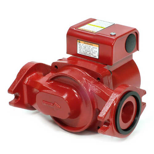
The "primary loop" is the boiler loop, in this case driven by the internal pump of the Navien, and it's flowing counter-clockwise. It's driving out the left-most port, so secondary loop flow (driven by the red pump) needs to be toward the tee branch node closest to the boiler's intake port, which it is (I think), and also flowing counter-clockwise. The pump looks like a Bell & Gossett, and with the pump motor on the top the arrow on the bottom of the housing would be pointed right, toward the bottom tee, not away(?). (You may have to get down on your knees to do the visual inspection on that.)
The fact that Navien's manifold has the tees pointed at the boiler, with the secondary loop going though the straighter, fatter pipe shouldn't much matter if the tees were space properly (which they aren't). It also doesn't really matter very much if the secondary pump is on the supply side or the return side, as long is the direction is correct.
So could it have been done better? Yes, no doubt!
But is it bad enough to be a real problem? Probably not.
If in some alternate left-handed spin universe the red pump is pumping away from the tee it's an easy fix. The flanges are symmetrical, and it can just be flipped around.
djdavenport
Member
Got it. Thanks, Dana. I got a little confused on your first post and somehow got the impression that the pump was pumping the opposite direction, AWAY from the tees, not towards them. Upon re-reading, it was obvious. I must confess, this stuff is really fascinating to me. I only wish I would have paid a little more attention in my college physics class. Cheers.
I have tried bleeding the watts manifold to reduce the pressure. I brought it down to about 14 psi (not much water needed to reduce the PSI I have realized). When the heat kicked in and the pumps circulated it quickly went down to 0.1 PSI on the navien once the pumps/boiler stopped. I added a little more pressure with the filler valve on the manifold up to 19 PSI. It is running fine at that PSI. I have messed around with removing pressure and then filling again to build pressure and I cannot get it to work at the 12 PSI range. When filling I have opened the air valve inside the Navien and also opened the pressure relief valve and then continued to add pressure once that water is ejected. I am not an expert at this but I think I am doing things correctly. This all started with a maintenance cleaning of the filters and then having to refill the pressure on the closed loop.
I could change the copper on the loop to match your guidelines above , I suspect that the installer put the tank in the current position due to the confined space. The pump position on the return side has always looked odd to me as it runs into the loop he made but as it runs in the correct flow (anti clockwise) that makes some sense. I have spent a lot of time looking for installations like this but to no avail. I appreciate your input and I am looking into hydraulic pressure online as I am not familiar with that.
I could change the copper on the loop to match your guidelines above , I suspect that the installer put the tank in the current position due to the confined space. The pump position on the return side has always looked odd to me as it runs into the loop he made but as it runs in the correct flow (anti clockwise) that makes some sense. I have spent a lot of time looking for installations like this but to no avail. I appreciate your input and I am looking into hydraulic pressure online as I am not familiar with that.
If the system is working OK there really isn't any point to re-plumbing the tee-manifold. It is NOT related to the sudden drops in pressure.
With only 4 gallons of water in the radiation and a small expansion tank it really doesn't take much water to reduce the pressure a couple psi, but it should take SOME. Are you sure the expansion tank was pre-charged ? The air pressure had to be brought up to snuff before it is installed on the system, not after, with no pressure bearing on it from the water side.
There is gobs of stuff written on the hydraulic separation, complete with the formal flow forumlae etc, but none of it matters too much on a simple 1-zone system. If the in to out temperature on the Navien is over 10F (and well under 50F) there is enough flow to heat the space, it's fine. It's more important when there are multiple zones and high flow zones when the secondary flows can change dramatically as calls for heat overlap (or don't), and with inadequate hydraulic separation those changes in flow interacting with the primary flow through the boiler can take the boiler out of it's optimal or safe operating zone, with either too much or too little flow.
With your one zone radiant system it may even be possible to run the Navien within spec pumping it direct with just a single pump (maybe even the pump that was shipped with it), but that would require doing the math ahead of time. With some amount of hydraulic separation (even if somewhat poorly implemented) there is a wider range of forgiveness, since the secondary flows can change quite a bit without changing the flow through the boiler too much.
Similar threads
- Replies
- 8
- Views
- 429
- Replies
- 0
- Views
- 145
- Replies
- 0
- Views
- 289