Wiring Well Pump

Users who are viewing this thread

Messages
58
Reaction score
0
Points
6
Location
Iowa
Hello everyone

I'm in the process of removing my well pit and would like to rewire the whole deal. I purchased a 30-50psi square D pressure switch with a Franklin 1 hp well control box. Needless to say both are very light on instructions - (virtually none) would anyone have a good guide to wiring one of these?

Also, my well head is about 200ft from my house and my well about another 120ft deep, my question is will a 20 amp breaker with standard 12 gauge wire handle 320 feet of run? (not sure if I termed that right but I know voltage drops off quite a bit).

Anyhow, I'm also putting in a new septic and just waiting for my permit and then time to rent a backhoe loader to remove well pit!

thanks!
 

Reach4

Well-Known Member
Messages
38,863
Reaction score
4,430
Points
113
Location
IL
With a 1 HP pump, 12 AWG is good for up to 400 feet according to the Franklin AIM manual. I suggest that you download that manual, because it may have some more good stuff for you. That includes "CONTROL BOX WIRING DIAGRAMS". Note there is more than one kind of Franklin 1 HP control box. Yours probably only has one capacitor because you ordered the cheaper one. That is what most people have.

For wiring the pressure switch, there are 4 terminals. One hot from the breaker goes to one of the left 2 screws. One hot goes to one of the right 2 screws. L1 goes to the remaining left screw. L2 goes to the remaining right screw. (or L2 on left and L1 on right is fine alternative.) So when the switch is on, the left two screws are connected together and the right two screws are connected together.

I would expect that you would be using UF cable. You might consider putting in another circuit or two for a convenient outlet while you are at it.

Who is going to weld the casing extension and install the pitless? If your casing is smaller than 5 inch, you will want to select a pitless that does not decrease the diameter for inserting the pump.
 
Last edited:
Messages
58
Reaction score
0
Points
6
Location
Iowa
Correction - the old control is a Franklin and the new box I purchased is a Wayne with zero instructions except for a wiring diagram on the lid but it's built exactly like the Franklin unit.

The Square D pressure switch came with instructions that literally fit on a business card.

These companies are making this way harder than it needs to be - I will check Franklin for control box instructions
 

Reach4

Well-Known Member
Messages
38,863
Reaction score
4,430
Points
113
Location
IL
well-pump-pressure-switch-wiring.jpg
 
Messages
58
Reaction score
0
Points
6
Location
Iowa

I'm just taking a bit of a guess here (instructions aren't too helpful) but my two hots connect to the center terminals on the pressure switch and then the outer two terminals connect to L1 and L2 of the control box?
 
Messages
58
Reaction score
0
Points
6
Location
Iowa
With a 1 HP pump, 12 AWG is good for up to 400 feet according to the Franklin AIM manual. I suggest that you download that manual, because it may have some more good stuff for you. That includes "CONTROL BOX WIRING DIAGRAMS". Note there is more than one kind of Franklin 1 HP control box. Yours probably only has one capacitor because you ordered the cheaper one. That is what most people have.

For wiring the pressure switch, there are 4 terminals. One hot from the breaker goes to one of the left 2 screws. One hot goes to one of the right 2 screws. L1 goes to the remaining left screw. L2 goes to the remaining right screw. (or L2 on left and L1 on right is fine alternative.) So when the switch is on, the left two screws are connected together and the right two screws are connected together.

I would expect that you would be using UF cable. You might consider putting in another circuit or two for a convenient outlet while you are at it.

Who is going to weld the casing extension and install the pitless? If your casing is smaller than 5 inch, you will want to select a pitless that does not decrease the diameter for inserting the pump.

Okay, the square d "business card" instructions are showing the center 2 terminals connecting to the motor and the outer 2 are L1 and L3. which makes no sense to me
 

Reach4

Well-Known Member
Messages
38,863
Reaction score
4,430
Points
113
Location
IL
Okay, the square d "business card" instructions are showing the center 2 terminals connecting to the motor and the outer 2 are L1 and L3. which makes no sense to me
Lets call the hot lines from the breaker box red and black. Lets call the lines to the control box L1 and L2. These are each OK for the 4 pressure switch terminals:
Red, L1, Black, L2
Red, L1, L2, Black *
L1, Red, Black, L2
L1, Red, L2, Black
Red, L1, L2, Black *
Red, L1, Black, L2
L1, Red, L2, Black
L1, Red, Black, L2
Red, L2, Black, L1 *
Red, L2, L1, Black
L2, Red, Black, L1
L2, Red, L1, Black
Red, L2, L1, Black *
Red, L2, Black, L1
L2, Red, L1, Black
L2, Red, Black, L1

here's the instructions that came with Square D http://www.homedepot.com/catalog/pdfImages/10/10a50e35-cbce-404b-bb26-b47ecaa8f957.pdf can anyone put these in Layman's terms
The other side of the sheet might be in English. The 4 lines that I marked with * above match the last diagram on the sheet that you scanned. The other 12 without the * would work too.
 
Last edited:
Messages
58
Reaction score
0
Points
6
Location
Iowa
Okay, so on the control panel the only wires connecting to L1 and L2 are from the pressure switch only -
 

Reach4

Well-Known Member
Messages
38,863
Reaction score
4,430
Points
113
Location
IL
Okay, so on the control panel the only wires connecting to L1 and L2 are from the pressure switch only -
Yes.

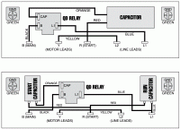
If you have a QD control box, the first of these two diagrams probably applies. From a wiring point of view, they are the same. If your UF is not black, red, yellow, green, just keep track of the colors that you do use.

I did see a post that says the well cap should connect to the green also if the well cap is metal.

Regarding the wiring of 4 wires to the pressure switch, of 24 permutations of how you could put 4 wires on 4 terminals, I think 8 are wrong.
 

Attachments

  • pix_1.GIF
    pix_1.GIF
    46.6 KB · Views: 1,674
Last edited:
Messages
58
Reaction score
0
Points
6
Location
Iowa
Okay, and from there the wires are color coded and easy to follow - I just didn't want to wire the switch incorrectly (now looks difficult to do) and burn something up and those instructions are not helpful IMO

Anyhow, this makes more sense - thanks everyone!
 
Messages
58
Reaction score
0
Points
6
Location
Iowa
"Who is going to weld the casing extension and install the pitless? If your casing is smaller than 5 inch, you will want to select a pitless that does not decrease the diameter for inserting the pump."


I believe I have a 6" steel well casing but I have not removed the cover to pull the drop pipe yet (picture attached). Anyhow, I'm thinking of cleaning up the pipe and welding an extension on myself - I would also be removing the concrete with a jackhammer. The biggest thing I've welded was a boat trailer (so far so good) how difficult will this be? Someone said these pipes are cast iron which are difficult to weld
 

Attachments

  • well.jpg
    well.jpg
    88.1 KB · Views: 825
Messages
58
Reaction score
0
Points
6
Location
Iowa
Also, if I need to run my wire overhead (well head is across street on lot I own) what kind of wire would be UV resistant? I would be using 12 gauge and the run to the well head is approx 200 feet. (I could run conduit under the street but there is a phone line under the street I would probably hit.

thanks!
 

Reach4

Well-Known Member
Messages
38,863
Reaction score
4,430
Points
113
Location
IL
I believe I have a 6" steel well casing but I have not removed the cover to pull the drop pipe yet (picture attached). Anyhow, I'm thinking of cleaning up the pipe and welding an extension on myself - I would also be removing the concrete with a jackhammer. The biggest thing I've welded was a boat trailer (so far so good) how difficult will this be? Someone said these pipes are cast iron which are difficult to weld

So there is some kind of pipe from the well under the road to the house already? I hope it is polyethylene. Steel adds rust. If this is your drinking water, I would replace the galvanized drop pipe with threaded schedule 80 PVC with stainless couplers. Use brass or stainless for fittings. However it is fair to ask what's the point if the horizontal pipe is going to stay galvanized. Is that a public road? How about burying a new poly pipe from the well to the house as part of your project? I think you could put the electric wires inside the same trench but higher. Nobody is going to bless your using low voltage landscape wire lashed to your service drop wire. I wonder how much extra a separate meter across the road would run you monthly.

How far is that well cap above the floor of the pit? It is likely the welding could be done without breaking up the floor. Even though nothing there is cast iron, I think you might want to find an experienced welder to extend your casing. I would not demolish the walls of the pit unless I were required to. I was required to demolish 2 walls. A big enough backhoe/excavator may be able to lift the top of the pit off fairly intact, so you would not need the jackhammer. The excavator they used did that, and they then buried my removed pit cover near the well so as to not have to haul it away.
 
Messages
58
Reaction score
0
Points
6
Location
Iowa
The pipe to the house is 3/4 copper and is about 60 years old (but appears in good condition).

It's either fix my current well or drill a new one and that would be a difficult DIY project
 

Reach4

Well-Known Member
Messages
38,863
Reaction score
4,430
Points
113
Location
IL
Copper is good. Is that running under a public road?
 
Top
Hey, wait a minute.

This is awkward, but...

It looks like you're using an ad blocker. We get it, but (1) terrylove.com can't live without ads, and (2) ad blockers can cause issues with videos and comments. If you'd like to support the site, please allow ads.

If any particular ad is your REASON for blocking ads, please let us know. We might be able to do something about it. Thanks.
I've Disabled AdBlock    No Thanks