GE Smartwater GXSF23Z01 wiring diagram

Users who are viewing this thread

creations15

New Member
Messages
28
Reaction score
0
Points
1
Location
Spokane
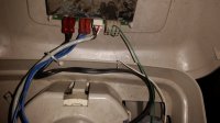
Good evening. Had the white wire unplug from the cover plate when cleaning the venturi which killed power to the unit Any ideas as to where it plugs into the board? Thanks

Keith
 

Mialynette2003

In the Trades
Messages
944
Reaction score
17
Points
18
Location
Ocala, Florida
If I'm not mistaken, the white wire goes to the micro switch which has 2 wires (red & white). This would not kill the power. The transformer has 2 black wires which will kill power if disconnected.
 

creations15

New Member
Messages
28
Reaction score
0
Points
1
Location
Spokane
If I'm not mistaken, the white wire goes to the micro switch which has 2 wires (red & white). This would not kill the power. The transformer has 2 black wires which will kill power if disconnected.

This is a picture of the white wire I'm talking about. It goes in the connector with the green wire.
 

Attachments

  • 20141222_092218.jpg
    20141222_092218.jpg
    51.8 KB · Views: 477

creations15

New Member
Messages
28
Reaction score
0
Points
1
Location
Spokane
So I plugged it to the left of the green wire and the unit will not stop draining water now for some reason. I have to manually bypass it as unplugging it doesnt stop the draining. Any ideas?
 

Mialynette2003

In the Trades
Messages
944
Reaction score
17
Points
18
Location
Ocala, Florida
The wire is used to indicate the position of the valve to the controller. With the wire disconnected, the controller thinks the valve is the service position when is fact it is in a one of the cycles. Push & hold the regen button to advance the unit into a cycle. Once the motor stops, push again. At some point the controller will take over & the motor will continue to turn until the controller & valve are in time. If the wire is not making good contact, the motor will contine to turn until an error code shows up on the display.
 

Mialynette2003

In the Trades
Messages
944
Reaction score
17
Points
18
Location
Ocala, Florida
Unplug, wait about 10 sec and plug back in. The motor will continue turning the valve until the valve & controller are in time or another error code pops up. If the error code pops up, the controller is not recieving a singal from the mirco switch.
 

creations15

New Member
Messages
28
Reaction score
0
Points
1
Location
Spokane
I appreciate it. Still getting ERR01. Is there a way to test the wire connection for a completion on the circuit? I spent quite a bit of time putting the wire into the connector so feel that it's connected. Just making sure it's in the right spot and all.
 

Mikey

Aspiring Old Fart, EE, computer & networking geek
Messages
3,024
Reaction score
17
Points
38
Location
Hansville, Washington
Dismount the circuit board the connector is on, and then 1) verify the position in the connector you've chosen is in fact connected to something, and 2) use an ohmeter to check continuity from the microswitch to the circuit board.
 

Mialynette2003

In the Trades
Messages
944
Reaction score
17
Points
18
Location
Ocala, Florida
I apologize, the correct position for the wire is on the inside. The 2 outside terminals are blank making the 2 inside in use.
upload_2015-1-9_18-16-34.png
 

creations15

New Member
Messages
28
Reaction score
0
Points
1
Location
Spokane
Can't thank you enough. The white wire was plugged into the other side according to past posts. Works perfectly. THanks!
 
Top
Hey, wait a minute.

This is awkward, but...

It looks like you're using an ad blocker. We get it, but (1) terrylove.com can't live without ads, and (2) ad blockers can cause issues with videos and comments. If you'd like to support the site, please allow ads.

If any particular ad is your REASON for blocking ads, please let us know. We might be able to do something about it. Thanks.
I've Disabled AdBlock    No Thanks