Duct Problems

Users who are viewing this thread

SAS

Member
Messages
324
Reaction score
12
Points
18
Location
Connecticut
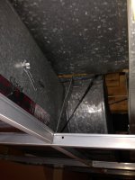
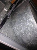
We have a problem with airflow to several rooms in our house. I have had a contractor look at it, and he has verified that there are no leaks or blockages in the supply or the returns, the blower is working as it should, but he has not been able to solve the mystery. There are two supplies off of a large horizontal rectangular duct that provide very strong air flow. After that there is a strange (at least to me) fitting in the main duct. It makes a 90 degree upward turn off of one side, goes over the top of the duct and then turns 90 degrees horizontally. At the same time it also reduces the size of the continuing horizontal duct. All of the supplies after that, whether they are off of the original (now reduced in size) duct, or the new duct running perpendicular to the original one, have very poor air flow.

The contractor admits that he would not have done it that way, but thinks that the only solution would be to redo the entire supply from the furnace, creating two separate feeds. Not only will this be very expensive, it will also require me to lower the ceiling in several places in the finished basement. I haven't received a clear answer as to why you wouldn't just tap the new duct off of the top of the existing one and hold off reducing the size for another few feet. That sounds straightforward to me, and it would seem as if it might permit more air flow. That said, I confess that I have no real knowledge of how to design HVAC systems. Am I missing something?
 

Reach4

Well-Known Member
Messages
38,858
Reaction score
4,428
Points
113
Location
IL
There are two supplies off of a large horizontal rectangular duct that provide very strong air flow. After that there is a strange (at least to me) fitting in the main duct. It makes a 90 degree upward turn off of one side, goes over the top of the duct and then turns 90 degrees horizontally. At the same time it also reduces the size of the continuing horizontal duct.
May I suggest that you post a photo or a sketch that illustrates what you are describing?
 

SAS

Member
Messages
324
Reaction score
12
Points
18
Location
Connecticut
May I suggest that you post a photo or a sketch that illustrates what you are describing?
I'll take some pictures tonight. I'm at work now, but I did try to find a picture of the fittings online without any success. That does further confirm my suspicions that this is not how it should be done.
 

Reach4

Well-Known Member
Messages
38,858
Reaction score
4,428
Points
113
Location
IL
That does further confirm my suspicions that this is not how it should be done.
Don't presume that I know how such things should be done. Those that do will be better able to understand your situation with a photo or two that illustrates the situation. 800 pixels and under about 24o kbytes or less if you want to upload to Terrylove.com, or whatever size if you have the pictures on a different site and link to them.
 

SAS

Member
Messages
324
Reaction score
12
Points
18
Location
Connecticut
Don't presume that I know how such things should be done. Those that do will be better able to understand your situation with a photo or two that illustrates the situation. 800 pixels and under about 24o kbytes or less if you want to upload to Terrylove.com, or whatever size if you have the pictures on a different site and link to them.
I took a couple of pictures, but it's hard to get a good shot. You can see how the first 90 degree bend comes off the side of the horizontal duct. What you can't see is that it runs vertically only far enough to clear the main duct and then makes a horizontal 90 degree turn so that it is now running perpendicular to the original duct and just above it.
 

Attachments

  • 2015-03-26 20.24.10.jpg
    2015-03-26 20.24.10.jpg
    67.4 KB · Views: 324
  • 2015-03-26 20.21.46.jpg
    2015-03-26 20.21.46.jpg
    93.4 KB · Views: 310

Dana

In the trades
Messages
7,889
Reaction score
509
Points
113
Location
01609
Your contractor who claimed to have "... verified that there are no leaks or blockages in the supply or the returns..." is full of it! Those ducts are all at least connected, but none look even close to being truly sealed.

Unless he gave it a duct-blaster pressurized test and MEASURED a low cfm leakage @ 25 pascals pressure (against expectations, based on the pictures) he hasn't a clue as to the actual leakage rate.

Before you do anything regarding booster fans, spend a day or so of "quality time" with your ducts, sealing every accessible joint & seam with duct mastic (you can buy it in tubs at box stores), and tape all of the seams on the air handler with a quality aluminum tape (Nashua 324a is available at most box stores, but there are others- just pick something with a temperature rating if you want it to stick for decades rather than months.)

Start with sealing the supply ducts, but don't neglect the returns, since it's the induced pressure difference between supplies & returns that delivers flow. It looks like you may have some panned joists as returns, some of which many need to be taped-over at the joist/metal transition first, then go over the tape with duct mastic for a reliable long term seal. The panned joist on that first picture looks like there is 1/4" or more of separation between the joist & steel, which is a pretty big leak. But any seam, no matter how tight it appears to be should get 1/8" or more of duct mastic troweled or brushed onto it.

The sealed ducts will be quieter and provide better flow. If that doesn't quite get you where you need to be, THEN start thinking about doing things like installing balancing vanes to restrict the flow slightly in the larger ducts, to better pressurize the narrower ducts.
 

SAS

Member
Messages
324
Reaction score
12
Points
18
Location
Connecticut
Your contractor who claimed to have "... verified that there are no leaks or blockages in the supply or the returns..." is full of it! Those ducts are all at least connected, but none look even close to being truly sealed.

Unless he gave it a duct-blaster pressurized test and MEASURED a low cfm leakage @ 25 pascals pressure (against expectations, based on the pictures) he hasn't a clue as to the actual leakage rate.

Before you do anything regarding booster fans, spend a day or so of "quality time" with your ducts, sealing every accessible joint & seam with duct mastic (you can buy it in tubs at box stores), and tape all of the seams on the air handler with a quality aluminum tape (Nashua 324a is available at most box stores, but there are others- just pick something with a temperature rating if you want it to stick for decades rather than months.)

Start with sealing the supply ducts, but don't neglect the returns, since it's the induced pressure difference between supplies & returns that delivers flow. It looks like you may have some panned joists as returns, some of which many need to be taped-over at the joist/metal transition first, then go over the tape with duct mastic for a reliable long term seal. The panned joist on that first picture looks like there is 1/4" or more of separation between the joist & steel, which is a pretty big leak. But any seam, no matter how tight it appears to be should get 1/8" or more of duct mastic troweled or brushed onto it.

The sealed ducts will be quieter and provide better flow. If that doesn't quite get you where you need to be, THEN start thinking about doing things like installing balancing vanes to restrict the flow slightly in the larger ducts, to better pressurize the narrower ducts.
Thanks for all of the advice. I do still have a question regarding that specific transition (and the pictures don't help all that much). The two supplies just before that fitting have great airflow, but everything after it, even a supply that is tapped off of that main duct a few feet past that fitting have minimal airflow. Is it possible that the transition itself is just providing such resistance that nothing after it has good airflow? If so, how would you re-do it?
 

DougB

Member
Messages
341
Reaction score
22
Points
18
Location
Minneapolis - Land of 10,000 taxes
Thanks for all of the advice. I do still have a question regarding that specific transition (and the pictures don't help all that much). The two supplies just before that fitting have great airflow, but everything after it, even a supply that is tapped off of that main duct a few feet past that fitting have minimal airflow. Is it possible that the transition itself is just providing such resistance that nothing after it has good airflow? If so, how would you re-do it?

There should be 'balancing' dampers in the duct work. Air will follow the path of least resistance.

An easy experiment would be to close ( if they have dampers, or block) the registers in the rooms where there is good airflow - then see what the airflow is like at the registers that had the weak airflo. If you get better airflow - try closing / blocking the good registers say half way - see what happens.

Another thing: is there a return in the vicinity of these problem rooms? You can't 'pump' air into a room, unless there is less pressure in the room (removed by the return air) than the duct.

An HVAC person would use a flow meter and adjust the duct dampers so they have the same static pressure (some grills larger than others will pass different CFM's).

Dana has good advice about sealing the ducts.
 

SAS

Member
Messages
324
Reaction score
12
Points
18
Location
Connecticut
There should be 'balancing' dampers in the duct work. Air will follow the path of least resistance.

An easy experiment would be to close ( if they have dampers, or block) the registers in the rooms where there is good airflow - then see what the airflow is like at the registers that had the weak airflo. If you get better airflow - try closing / blocking the good registers say half way - see what happens.

Another thing: is there a return in the vicinity of these problem rooms? You can't 'pump' air into a room, unless there is less pressure in the room (removed by the return air) than the duct.

An HVAC person would use a flow meter and adjust the duct dampers so they have the same static pressure (some grills larger than others will pass different CFM's).

Dana has good advice about sealing the ducts.
I have done that experiment and it does not change the airflow in those rooms. Interestingly, one of those room has one supply before that odd double 90 degree reducing fitting and one after. The one before that transition has great airflow, the one after it has very minimal airflow. That, I think, eliminates the return as the cause of my problem. The experiment that I would like to do, but I will have to pay someone to do it, is to remove that fitting altogether to see if the airflow to everything downstream improves. I guess, first I should cut off the branch that leads off of that fitting to make sure that it is not somehow "absorbing" all of the airflow. If it is that fitting, then is it possible to connect one rectangular duct to a main duct that is running perpendicular to it from above (there is a steel beam alongside it, so I can't connect on the side)?
 

Dana

In the trades
Messages
7,889
Reaction score
509
Points
113
Location
01609
A sketch of the duct layout indicating all of the ells/tees, lengths and changes in duct size (estimate the cross sectional areas in square inches) might be useful. But if closing down all of the high flow registers doesn't improve air flow in the other branches there is either major leakage (which should be detectable without a duct-blaster) or an obstruction, such as a stuck balancing vane, a large cat, etc.
 

DougB

Member
Messages
341
Reaction score
22
Points
18
Location
Minneapolis - Land of 10,000 taxes
I have another thought - maybe there is something stuffed in the duct? I've heard of rodents building nests. Can you take off a grill, and get an inspection mirror? or a plumbers snake?
 

Reach4

Well-Known Member
Messages
38,858
Reaction score
4,428
Points
113
Location
IL
I have another thought - maybe there is something stuffed in the duct?
I think that is what Dana meant by " large cat, etc.". At first I was wondering if he was referring to a catalytic converter, but not for long.
 

Dana

In the trades
Messages
7,889
Reaction score
509
Points
113
Location
01609
A fiber-optic camera could be used to visually inspect remote areas behind all the twists & turns, if you have access to one.

Where ducts make multiple turns in short distances the turbulence & eddies can sometimes deposit debris reduceing the effective cross section too. A 1/4" drill hole into the ells might determine if that's what's going on. (A blob of duct mastic smeared 1/2" around/over and 1/16" deep a probe hole like that is sufficient to plug the drill hole leak.)
 

SAS

Member
Messages
324
Reaction score
12
Points
18
Location
Connecticut
A fiber-optic camera could be used to visually inspect remote areas behind all the twists & turns, if you have access to one.

Where ducts make multiple turns in short distances the turbulence & eddies can sometimes deposit debris reduceing the effective cross section too. A 1/4" drill hole into the ells might determine if that's what's going on. (A blob of duct mastic smeared 1/2" around/over and 1/16" deep a probe hole like that is sufficient to plug the drill hole leak.)
The contractor cut out sections and patched them with sheet metal to look for any blockages. I'm not sure that was even necessary. Since before the split to the second duct air flow is fine, but on both branches the first supply has poor airflow, I'm fairly certain that it's the way the two ducts are joined that is causing the problem. I just don't know how it can be done differently. I guess I'll have to try and find another HVAC guy. Any suggestions on how to find one who really understands how to redesign the ducts?
 

Reach4

Well-Known Member
Messages
38,858
Reaction score
4,428
Points
113
Location
IL
I suggest that you see reply #11 regarding the sketch.

In particular sketch the stuff in the photos. The photos don't tell the story as well as we would hope.
 

SAS

Member
Messages
324
Reaction score
12
Points
18
Location
Connecticut
I suggest that you see reply #11 regarding the sketch.

In particular sketch the stuff in the photos. The photos don't tell the story as well as we would hope.
I agree - the photos are not very helpful. I'll try to sketch it out.
 

Dana

In the trades
Messages
7,889
Reaction score
509
Points
113
Location
01609
The contractor cut out sections and patched them with sheet metal to look for any blockages. I'm not sure that was even necessary. Since before the split to the second duct air flow is fine, but on both branches the first supply has poor airflow, I'm fairly certain that it's the way the two ducts are joined that is causing the problem. I just don't know how it can be done differently. I guess I'll have to try and find another HVAC guy. Any suggestions on how to find one who really understands how to redesign the ducts?

Unless the guy sealed the sheet metal patches with duct mastic (or at least aluminum foil tape?) he just added a bunch of air leakage to your duct system.

A competent duct contractor wouldn't balk at quoting what it takes to reconfigure the ducts so that the design complies with ACCA Manual-D. If they can't explain what the basic concepts of Manual-D are over the phone,it's time to move on to the next number on your list- they're just another tin-banger.
 

SAS

Member
Messages
324
Reaction score
12
Points
18
Location
Connecticut
Unless the guy sealed the sheet metal patches with duct mastic (or at least aluminum foil tape?) he just added a bunch of air leakage to your duct system.

A competent duct contractor wouldn't balk at quoting what it takes to reconfigure the ducts so that the design complies with ACCA Manual-D. If they can't explain what the basic concepts of Manual-D are over the phone,it's time to move on to the next number on your list- they're just another tin-banger.
The patches are all well-sealed. Just so I know before I ask about it - what is ACCA Manual-D? I don't expect you to quote it back to me, but what kind of things does it specify? Is it a methodology for configuring ducts, or some series of computations for ensuring adequate airflow?
 

Dana

In the trades
Messages
7,889
Reaction score
509
Points
113
Location
01609
I gave you a links to click on to educate yourself about Manual-D basics. Click on it, pore over it a bit, you'll get the gist of it. It's really all of the above- configuration, sizing, calculating the air flows based on all duct impedances, including turns, etc.

If you're more of a visual & auditory type learner and want to know more way about it than the average tin-banger, watch this. (You'll need an espresso- it's painfully dry nerd-speak, but not targeted toward engineers with too much math) You can fast-forward to the 5:00 minute mark.

The contractor doesn't have to do the whole duct design, but if they are capable of Manual-D designs they should be able to debug what's going on with yours pretty quickly and would likely recommend a solution that actually works.
 
Top
Hey, wait a minute.

This is awkward, but...

It looks like you're using an ad blocker. We get it, but (1) terrylove.com can't live without ads, and (2) ad blockers can cause issues with videos and comments. If you'd like to support the site, please allow ads.

If any particular ad is your REASON for blocking ads, please let us know. We might be able to do something about it. Thanks.
I've Disabled AdBlock    No Thanks