Chlorinator help

Users who are viewing this thread

Robert Nollkamper

New Member
Messages
5
Reaction score
0
Points
1
Location
Austin, TX
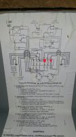
Hi, I've been a lurker for some time, but this is a first time post. I moved into this house a little over a year ago, and the water smelled like sulfur. I decided to make some upgrades to the well, so I put in a CSV1W, Stenner Chlorinator, softener, carbon filter; everything was fine until My Stenner started making a bunch of racket about 2 months ago, and now my Overload switch has reset a couple times on my well. I tested the run capacitor and it isn't happy. I'm wondering if the way I connected the stenner pump could have caused premature failure to both it and the capacitor. Could someone tell me if there is a better way to connect it?
 

Attachments

  • Screenshot_2015-08-05-08-49-37.jpg
    Screenshot_2015-08-05-08-49-37.jpg
    71.2 KB · Views: 219

Reach4

Well-Known Member
Messages
38,892
Reaction score
4,435
Points
113
Location
IL
That diagram is not for a Senner chlorinator pump. I would be surprised if your Stenner pump uses a run capacitor. http://stenner-pumps.com/pumps.htm#a has installation manuals. The motors are replaceable.

This system presents a problem: with a CSV1A, the flow might be 8 GPM and it might be 1 GPM. Adjusting the right rate of chlorination will be a problem. Also, are you chlorinating and filtering the water you use for the outside hose faucets? A proportional Chlorinator would seem to avoid the problem of trying to adjust the the chlorination for variable flows.
 

Robert Nollkamper

New Member
Messages
5
Reaction score
0
Points
1
Location
Austin, TX
I'm sorry, I didn't specify...this runs at about 10GPM and fills a cistern...its consistent as far as i can tell. The CSV runs on a booster pump to the house; totally separate system...the stenner runs on the well that fills the cistern (the diagram I posted), and I measured about 10GPM. My primary question is that I Dont know if, since the well is a start-run capacitor system, that would damage anything by tapping into the well output of the control box. Is there a better way, on my exact system, to connect the stenner? I feel like the capacitors make problems for the stenner (words like phase shift scare me!) The diagram on stenner instructions have me tap into the pressure switch, but the pressure switch controls the booster pump, a totally different system.

P.S. the switched output for the diagram is a float switch in the cistern.
 

Valveman

Cary Austin
Staff member
Messages
14,633
Reaction score
1,303
Points
113
Location
Lubbock, Texas
Website
cyclestopvalves.com
That is a good way to do it. The output of the booster pump and CSV are not related to the chlorine injector. I see no problem with the way the chlorinator is wired. If the well pump is tripping the overload, it maybe pumping the well dry, which is not good for it. You may need to restrict the flow from the well pump or use a Dry Well protector like the Cycle Sensor to protect the pump.
 

Robert Nollkamper

New Member
Messages
5
Reaction score
0
Points
1
Location
Austin, TX
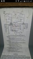
I have thought maybe here, at L2 and SW, that wouldn't be capacited. but as I look at the diagram, it goes through contactor windings and overload switch...I Dont know if adding 1A to that circuit would cause problems
 

Attachments

  • Screenshot_2015-08-05-10-32-37.jpg
    Screenshot_2015-08-05-10-32-37.jpg
    73.2 KB · Views: 234

Robert Nollkamper

New Member
Messages
5
Reaction score
0
Points
1
Location
Austin, TX
Thanks valveman! Omit my last diagram "proposal". I doubt the well is dry, this well has been in operation this way for 3 years with no trouble until now; and we had a lot of rain here in Central Texas at the beginning of the year that brought the aquifer levels up; but I'm not the expert! Im going to swap the capacitor as soon as I can, and if I still have a problem with the overload tripping, then I'll address it!

P.S. I have a "pump saver" before the control box. I was under the impression that prevented from running dry, but I could be wrong.
 

Valveman

Cary Austin
Staff member
Messages
14,633
Reaction score
1,303
Points
113
Location
Lubbock, Texas
Website
cyclestopvalves.com
After a second look I think the chlorinator would be better connected to the L1, L2 as the second diagram shows. This would separate it from the well pump capacitors. I don't think the chlorinator would hurt the capacitors, but it doesn't need to connect to them.
 

Reach4

Well-Known Member
Messages
38,892
Reaction score
4,435
Points
113
Location
IL
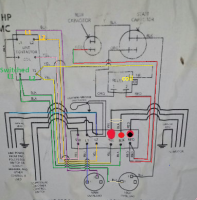
I think you need to power your pump between yellow and black. Only the red wire will be affected by the capacitors. I agree that the power will add to what the main overload carries. While I expect the extra amp will not trip the main overload since that controller is made to work with a range of pumps, I am not sure.
 

Attachments

  • img_2.png
    img_2.png
    192.8 KB · Views: 262

Robert Nollkamper

New Member
Messages
5
Reaction score
0
Points
1
Location
Austin, TX
Reach, I was mistaken...it is connected to yellow and black. It has worked fine for 9 months, so it could just be coincidence that the stenner and capacitor are going out around the same time. I know enough electrical to get myself into trouble, but not enough to fix it when it breaks! I'm much more of a 12VDC kind of guy, as an auto technician. Thanks guys, for your help!
 

Reach4

Well-Known Member
Messages
38,892
Reaction score
4,435
Points
113
Location
IL
Run capacitor should last indefinitely. I think it is a coincidence. The start capacitor will go bad eventually for sure.
 
Top
Hey, wait a minute.

This is awkward, but...

It looks like you're using an ad blocker. We get it, but (1) terrylove.com can't live without ads, and (2) ad blockers can cause issues with videos and comments. If you'd like to support the site, please allow ads.

If any particular ad is your REASON for blocking ads, please let us know. We might be able to do something about it. Thanks.
I've Disabled AdBlock    No Thanks