DWV project - how does this look?

Users who are viewing this thread

Sbmmm

New Member
Messages
20
Reaction score
1
Points
3
Location
Arizona
I have attached a pdf of the floorplan and pictures in its current state. The house is in Arizona and it's a conversion of an old addition into a larger new space with additional plumbing fixtures.

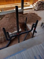
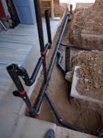
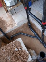
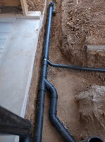
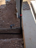
  • Existing 3" drain line leads to the house main, then to the city main. A cleanout furthest downstream of the addition space is visible in at least one photo. Just upstream of the cleanout is the beginning of the new DWV plumbing.
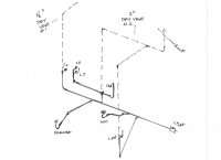
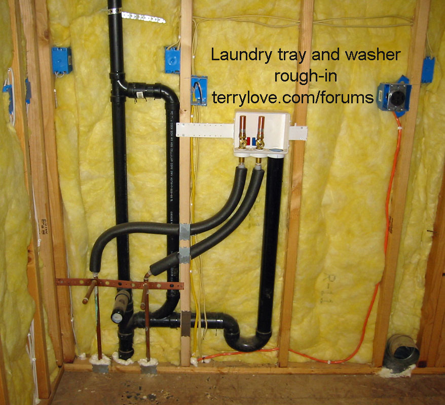
  • Above (approximately) the new 3" drain line will be the wet wall servicing the bath group (Shower, Lav and WC) on one side and the laundry group (CW standpipe and LT) on the other side.
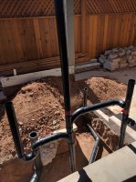
  • The current design lays out the following, from upstream to downstream -
2" vent with cleanout -->
Shower -->
CW and LT on a back-to-back fitting with 2" vent reducing to 1 1/2" vent above the ceiling -->
Toilet -->
Lav -->
Existing cleanout outside
1. Do all the fittings look correct?
2. Should the toilet be fitted further downstream of the Lav (or upstream of the others)?
3. Do the vent positions look correct?
4. Because there are preexisting roof penetrations for 2" and 1 1/2" vents, can I tie them together on the same vent circuit? or should I vent the CW and LT independently by using the 1 1/2" penetration and then use the 2" penetration for the bath group?
5. What should I install/use for testing during inspection? Should I add a separate tee where the new and old plumbing meet in order to insert a balloon/bladder?
6. Does air pressure testing happen at this stage as well as the water test?

I'm sure I will have more questions, but any advice is appreciated.
Photo Jul 05, 11 54 44 AM.jpg

Photo Jul 05, 11 53 32 AM.jpg
Photo Jul 05, 11 54 12 AM.jpg
Photo Jul 05, 11 54 59 AM.jpg
 

Attachments

  • 850_close-up_plumbing-Floor Plan.pdf
    43 KB · Views: 261
Last edited:

hj

Master Plumber
Messages
33,603
Reaction score
1,042
Points
113
Location
Cave Creek, Arizona
Website
www.terrylove.com
It would nice if you had the fitting stuck together so we can see how you are actually going to install them rather than assuming they are going in correctly. Your wife is going to hate you if you put that sink between the washer and dryer.
 

Sbmmm

New Member
Messages
20
Reaction score
1
Points
3
Location
Arizona
The reason I didn't stick everything together was because I wasn't sure of two things. One, should the toilet be connected to the 3" pipe where it is or should I position it more upstream or downstream relative to other fixtures? And two, I am not familiar with the DWV testing requirements for the City of Phoenix inspectors. Specifically, where the old pipe meets the new (both are ABS), should I add a 3" tee with a cleanout just for the sake of adding a balloon for testing (and cap everything else with cheap knockout plugs)? The screw plug for the existing cleanout is on a riser about 18" above the 3" pipe so I'm guessing an "affordable" balloon doesn't work there. Or another option, maybe I temporarily elevate the whole glued set (as one piece) so it's high enough to cap the transition end too with a better testing cap. I don't like my second suggestion as much because there seems to be more room for mistakes when making the final connection by altering, even slightly, the final fixture positions. Maybe I'm wrong there, but I would rather glue each segment piece by piece, checking for pitch, positioning, etc., as I go. DWV specific work is new to me, although plumbing is not.

What is the best way to prepare for inspection at this stage? Also, is there an air pressure test at this stage? Or is it one or the other?

When I have a specific plan, I will make exact cuts and dry fit for another picture. I was just hoping that enough could be discerned from my take-off to help answer the questions that affect measurements and cuts. Thanks for the help.
 
Last edited:

SST!

New Member
Messages
5
Reaction score
0
Points
1
Location
Massachusetts
I would consider a sand bed for those pipes, a couple of inches of sand will hold those pipes in place for dry fit, and final glue too.
 

MKS

Member
Messages
259
Reaction score
22
Points
18
Location
Illinois
Listen to HJ.
If abs is like pvc you can not "accurately" cut your pipe to length and dry fit. The solvent weld process allows the pipe to bottom in the fitting. The pipe should not bottom in the fitting dry.
Mock it up long to indicate your intentions. Post pictures of this. This should allow HJ and others who know well what they are looking at to give advice.
You might call the office of the inspector but you won't know till one arrives.
And if you have not already, make some practice joints using the instructions.
 

Sbmmm

New Member
Messages
20
Reaction score
1
Points
3
Location
Arizona
Listen to HJ.
If abs is like pvc you can not "accurately" cut your pipe to length and dry fit. The solvent weld process allows the pipe to bottom in the fitting. The pipe should not bottom in the fitting dry.

This is one reason why I laid out the mock-up like I did. The other is...

Mock it up long to indicate your intentions.

I don't know what is best practice regarding the connection location for the toilet. Specifically, is it better downstream of the Lav or upstream of everything else or leave it where it is? That dramatically affects the layout of the 3" waste pipe and where cuts are made for the connecting wyes. Actually, it affects almost every branch measurement as well if the wye locations change. That's why I asked these questions in advance of cutting. I thought my mock-up showed enough to provide those type of answers.

From what I can find doing more research, I will buy a test tee with cleanout to attach the old and new ABS. Then I will use a stoppage balloon at the test tee for testing the new work and just cap it and bury it afterward (even though there is a two-way cleanout tee with an 18" riser one foot from this connection). It's still a little cheaper than the long balloon I've seen as the alternative. Unless there is another suggestion for testing, this is where I'm headed.

If I can get few of these preliminary questions answered, then I will have a better sense for the best fitting locations. Off of that, I will run the pipe sections long in order to provide a clearer mock-up. Any answers or suggestions at this point? Thanks.
 

CountryBumkin

Active Member
Messages
915
Reaction score
70
Points
28
Location
Orlando, FL
You should provide a drawing of your plan like this one (borrowed from another member's post) - so the plumbing experts here can comment. It's too hard to figure out what your doing based on the photos. The type of fitting, angle, location of vent, size of pipe, etc., is all critical to a properly designed/function system (and to pass inspection).
Perhaps you can use the drawing you provides and add/draw in the plumbing (pipe runs and locations) and fittings you plan to use.

upc_wet_venting_bathrooms.jpg
 

MKS

Member
Messages
259
Reaction score
22
Points
18
Location
Illinois

Sbmmm

New Member
Messages
20
Reaction score
1
Points
3
Location
Arizona
Ok, I have returned back from a break from the Phoenix summer heat. I sketched a schematic showing the layout with venting and have included pictures of the dry fit mock-up. I cut the pieces long and as a result, they are not orientated exactly at the correct pitch. They will be when glued.

Notes:
1. I decided to keep the original floorplan as included above, with the LT in between the clothes washer and dryer.
2. If it helps, the location of the two existing vent penetrations can be seen in the floorplan file at the top of the post.
3. Dry vent #1 is identified as 1 1/2", but I am using 2" pipe up to the underside of the roof. I have a Fernco reducing clamp to attach the ABS to the galvanized pipe going outside. If required, I can make this penetration 2" to accommodate a full 2" need.
4. In the mock-up pictures, I put red masking tape at the beginning of each vertical dry vent pipe to clearly identify each location.

Pipes and fittings:
-3" pipe and fittings are used for the WC and main drain line.
-2" pipe and fittings are used for the shower, the clothes washer and LT, including the back-to-back fitting (but the LT san-tee has a 2" bottom with 1 1/2" and 1 1/2" for each of the other two joints, allowing a street 90* to terminate with a 1 1/2" cleanout to service the LT line).
-1 1/2" pipe and fittings for the Lav.
- Above the upstream bend, a 3"->2" reducer is used, leading to the 2" san-tee and cleanout.
- The 3" wyes that lead to shower and lav have 2" and 1 1/2" joints/arms, respectively.
- Below the back-to-back fitting is a 3" Combo fitting on the main drain line with a 2" joint/arm to accommodate the 2" vertical pipe.

Questions:
1. Is the venting, as illustrated sufficient and in the correct positions?
2. Does the 1 1/2" vent penetration in the roof need to be enlarged? (hopefully not, but doable)
3. I could combine both vent pipes above the ceiling, thereby having a 2" penetration and a 1 1/2" penetration on the same vent circuit? Would that be beneficial?
4. Could I enlarge the branch drain line from the Lav from 1 1/2" to 2" and turn that into a wet vent and thereby, eliminate the need for a dedicated dry vent above the Lav line?
5. In order to pass inspection, I purchased a threaded rubber balloon to use in the cleanout tee at the old and new junction and plugs to use in every other opening except where I'll add the water. Does there usually need to be a vertical column of pipe of a certain height when adding the water for inspectors? (I municipalities have different code books, etc., but generally?)

Any other suggestions/corrections? Thanks.
 

Attachments

  • 850_plumbing_vents_02.jpg
    850_plumbing_vents_02.jpg
    27.5 KB · Views: 466
  • IMG_20160724_125302.jpg
    IMG_20160724_125302.jpg
    110.4 KB · Views: 374
  • IMG_20160724_125318.jpg
    IMG_20160724_125318.jpg
    119.6 KB · Views: 388
  • IMG_20160724_125410.jpg
    IMG_20160724_125410.jpg
    125 KB · Views: 382
  • IMG_20160724_125438.jpg
    IMG_20160724_125438.jpg
    122.7 KB · Views: 389
  • IMG_20160724_125501.jpg
    IMG_20160724_125501.jpg
    109.4 KB · Views: 373
Last edited:

Sbmmm

New Member
Messages
20
Reaction score
1
Points
3
Location
Arizona
It would nice if you had the fitting stuck together so we can see how you are actually going to install them rather than assuming they are going in correctly. Your wife is going to hate you if you put that sink between the washer and dryer.

I have assembled the mock-up as you suggested and included a drawing schematic to view the overall system with vents. I am guessing there are at least 5 things wrong with what I have shown. Probably more. What do you think is wrong and what could be improved? Of course, others can offer constructive criticism, as well. All input is welcome. Thanks.
 
Last edited:

Reach4

Well-Known Member
Messages
38,858
Reaction score
4,428
Points
113
Location
IL
The A, B, C area is a problem. Item B appears to be is a sanitary tee to service a sink or something. If so, there is no vent.

Fixture D I think is a dual fixture fitting. Then C would be a trap arm? The drain into the trap arm cannot come from above or below. So if B is coming from a P trap, that would have to all be on the same level (except for the 2% slope) as the C pipe.

Maybe make A a tee that goes up and over to the vent above D joining 6 inches or more higher than E and the top of the highest sink there. Now could C continue to be used as a pure drain into the dual fixture fitting? I would guess so, but I am not a plumber.

While you could raise the standpipe and D to the height of the sink P trap output or lower the sink P trap output down to the height of D, having them on different levels with separate vents would be better to have a powerful washer not be able to send water up into the sink.

img_3.jpg
Red tape such as F seems to represent vent lines. You probably said that.

Standpipe looks nice.
 

Sbmmm

New Member
Messages
20
Reaction score
1
Points
3
Location
Arizona
Thanks for the response.

" Item B appears to be is a sanitary tee to service a sink or something. If so, there is no vent."
In this design, B is a san-tee but only to accommodate cleanout in the top opening using a street 90*. Doesn't the vent above D provide air for E and B?

"Fixture D I think is a dual fixture fitting."

Yes, item D is a back-to-back fitting. I knew, if rotated 90*, it could service two fixtures at the same level on different sides of the wall, but in this design, I'm using it for two two fixtures on only one side and I vertically orientated A and B to accommodate an extra cleanout for the LT. Normally, it would probably just take a horizontal 90* at the end of C to accept the trap arm (without a CO). If it's a problem, I will just forget the CO or add it separately on C. I also wonder (I know this is big taboo IF connected to extended drainage lines), but could I use the san-tee horizontally with the street 90* and cleanout at the end of C? IOW, attach B and A at the end of C so it's all horizontal?

Is it against code (or best practice) to use the back-to-back like I did in this design? It doesn't seem so because the turn radius of the opposing outlet arms is more of a long turn design. There could be some specific reason that code prohibits it, but I don't know. In the new mock-up I separated the drainage fittings (I didn't have extra 2" san-tees so I used 2" combos, but the separated drainage idea is there).

And yes, red tape above D and F represent the vertical dry vent lines. Actually, below F is also acting as a dry vent, but provides an end-of-line cleanout at F. The red tape is just a visual aid.

I am attaching a new mock-up picture, making a few changes to consider. Any comments would be helpful. Thanks
 

Attachments

  • IMG_20160726_094358.jpg
    IMG_20160726_094358.jpg
    125 KB · Views: 359
Last edited:

Reach4

Well-Known Member
Messages
38,858
Reaction score
4,428
Points
113
Location
IL
1. I think the horizontal coming from the sink need to be a sanitary tee (AKA santee). The sanitary tee allows vent air to enter from above into the horizontal pipe in addition to letting water fall to the drain pipe. That fitting you show in this latest picture would be for a line that is already vented.

2. Now that you have separate drain heights on the horizontals, you will need a vent from above into the horizontal for the standpipe.

You will see example pictures in the following threads. See how there are separate vent lines that go horizontal and join at least 6 inches above the flood level of both the standpipe and the sink.

https://terrylove.com/forums/index....d-pipe-drop-in-sink-dwv-stack-question.45231/

https://terrylove.com/forums/index.php?threads/washing-machine-slop-sink-aav.46581/
 

Sbmmm

New Member
Messages
20
Reaction score
1
Points
3
Location
Arizona
Thanks again. I appreciate your response because it means this is getting a step closer. I need to make all design corrections now and then make final cuts, glue, test and then call for inspection of the DWV.

I was confused because I read this (see section 908, pages 21 and 22 of the pdf) - http://www.plumbingpros.com/pdf/dwvents.pdf

And as I read this post (within the link you provided), I saw Terry's comment here - https://terrylove.com/forums/index.php?threads/washing-machine-slop-sink-aav.46581/#post-340414

It seems a back-to-back can be used, but it seems to be conditional in certain jurisdictions. In Phoenix, UPC 2012 "or" IPC 2012 is used (per the permit). In the 2012 UPC code book and I could be wrong, but it says here in section 905.6 - https://archive.org/stream/2012UPC/2012 UPC#page/n151/mode/2up/search/908

But is Terry's picture example better practice? I will gladly deviate from my CW and LT design and copy Terry's if it better fits into my larger DWV design. No two (DWV) designs are exactly alike, but it seems I could copy Terry's and bump the venting over from where I had it.

What to do ???
 

Reach4

Well-Known Member
Messages
38,858
Reaction score
4,428
Points
113
Location
IL
Copying Terry's example is a sure way to do it well.

Using the double fixture fitting requires the two trap arms to be at the same height. Plus it has the extra possiblity that the washing machine could blow suds into the sink. Adding the extra vent to let the heights be just where you like is not a big deal, and we know that you are not lazy or afraid to buy some extra ABS!
 

Sbmmm

New Member
Messages
20
Reaction score
1
Points
3
Location
Arizona
Thanks again. I am still wondering why my picture attached in post #12 above wouldn't work (with 2" san-tees instead of combos)? But, I can use Terry's design, https://terrylove.com/images/washer_rough_b.jpg
since it's deemed better practice here. And it's not too much extra ABS to loop back up and re-vent above 42". BTW, I always like to buy more materials if possible and return what's not used to avoid trips to the store. Those small trips kill me. The only thing I dislike more is three putting.

The bigger questions are asked in post #9 above as I need to keep moving,
https://terrylove.com/forums/index.php?threads/dwv-project-how-does-this-look.66185/#post-493543
Specifically, I provided a dry fit mock-up and drawing schematic (both as suggested) and people are logging on and logging off without answering these questions.
 

Reach4

Well-Known Member
Messages
38,858
Reaction score
4,428
Points
113
Location
IL
I am still wondering why my picture attached in post #12 above wouldn't work (with 2" san-tees instead of combos)?
By the rules, the pipe into the top of lower santee would not be considered a proper vent, although in practice I suspect it would work fine as a wet vent.
 

Terry

The Plumbing Wizard
Staff member
Messages
29,942
Reaction score
3,459
Points
113
Location
Bothell, Washington
Website
terrylove.com
Post 12 wet vents the sink over the washer.
They don't allow that anymore.
Also, you have combo's on the vertical, which creates an S trap that siphons the traps.
Keep those a santee.
If you are adding a vent to a horizontal trap arm, then you would have the combo on it's back. Then venting is from above, not below.
 

Sbmmm

New Member
Messages
20
Reaction score
1
Points
3
Location
Arizona
Post 12 wet vents the sink over the washer.
They don't allow that anymore.
Also, you have combo's on the vertical, which creates an S trap that siphons the traps.
Keep those a santee.
If you are adding a vent to a horizontal trap arm, then you would have the combo on it's back. Then venting is from above, not below.

Thanks, Terry (and Reach for your responses).

Ok, I can understand that sink over washer is no longer permitted. I have been referencing different code books/years. What about a back-to-back fitting at the same level? Or is your design mentioned above in post #16 preferable (all else being equal)?

It's been a moving thread, I know, but I did clarify earlier that I didn't have two extra san-tees for the dry fit mock-up, but I would use them if I separated the horizontal drains in this way.

The much bigger questions are contained in post #9 for the overall DWV design. I want to finish the below slab work so I can get it tested and inspected to continue on. I'm sure that I have made mistakes, but I would like to correct them now. I appreciate it.
 

Terry

The Plumbing Wizard
Staff member
Messages
29,942
Reaction score
3,459
Points
113
Location
Bothell, Washington
Website
terrylove.com
You can use a double fixture cross for a sink and washer.

My parents used to have a double sancross for their washer and sink.

It did a real number on the floor with all the flooding. I changed all that when I became a plumber. And I replaced the floor.
 
Top
Hey, wait a minute.

This is awkward, but...

It looks like you're using an ad blocker. We get it, but (1) terrylove.com can't live without ads, and (2) ad blockers can cause issues with videos and comments. If you'd like to support the site, please allow ads.

If any particular ad is your REASON for blocking ads, please let us know. We might be able to do something about it. Thanks.
I've Disabled AdBlock    No Thanks