WaterGroup STF20-860 Program dial not moving

Users who are viewing this thread

dss_cottage

New Member
Messages
10
Reaction score
0
Points
1
Location
Ontario
I have a WaterGroup STF20-860 combination water softener and tannins filter. It is about 4 years old and has been working well.

However, it now does not automatically regenerate. However, it will manually regenerate.

It appears that the program wheel is not rotating as water is used. Therefore it does not trigger the automatic regeneration.

We live in a remote area about 100 km away from the company that will service the unit.

Before we incur a very expensive service call, is there anything that I can do fix the problem myself?
 

Reach4

Well-Known Member
Messages
38,903
Reaction score
4,438
Points
113
Location
IL
Does your controller look like this? If not, I suggest that you post a photo of the controller with the controls as visible as you can do easily. Maybe post the photo anyway. pix_4.GIF
 

dss_cottage

New Member
Messages
10
Reaction score
0
Points
1
Location
Ontario
Does your controller look like this? If not, I suggest that you post a photo of the controller with the controls as visible as you can do easily. Maybe post the photo anyway. View attachment 28220

Yes. The controller looks like your picture. I'll post a picture.

In answer to Noyzee1...
I'm fairly technically competent and I have time.
 

Attachments

  • softener.jpg
    softener.jpg
    107.4 KB · Views: 341

Noyzee1

Member
Messages
32
Reaction score
4
Points
8
Location
SoAz
Well, then, I would ascertain why the dial is not moving. Using the diagram above, see if you can determine whether the flow meter is working and the turbine inside is rotating.
You would probably do well to bypass the unit and remove the flow meter, which can be inspected and rebuilt. There could be something blocking the turbine or some contamination. Maybe the sensor in the turbine assembly is bad? Or is it a mechanical linkage?
Others that know this valve well can chime in with more specific info, but I say read the manual and start diggin' in.
Sorry for not giving you more specifics, but I'm not familiar with that valve (yet).
Cheers,
JIM
 

Akpsdvan

In the Trades
Messages
1,542
Reaction score
15
Points
38
Location
Alaska
Fleck 2510 valve with right angle meter dome.

Could be that the meter cable is un hooked at either the dome or down in the right hand lower corner of the 3210 timer assembly.
Or the paddle wheel is stuck and will need to be cleaned.

Stuffed into the middle of the floor joists is going to make working on it a challenge but it can be done...
 

Bannerman

Well-Known Member
Messages
4,850
Reaction score
793
Points
113
Location
Ontario, Canada
There is a mechanical cable directly behind the control, that is connected to a turbine impeller while the opposite end is connected to the valve control. The cable turns (twists) as the turbine spins, which then turns the lower right toothed wheel (marked 'Capacity Gallons'), advancing the gallon count when water is flowing to your plumbing fixtures.

The cable can be pulled straight out (usually upwards) from the turbine housing as it is a single cable that simply 'plugs in' to the turbine. Disconnect the cable from the turbine to make sure the cable is not damaged and is able to be turned freely and ensure that twisting the cable by hand, will move the 'capacity gallons' wheel.

Most likely, some debris is caught in the turbine so you can proceed as Noyzee suggested in bypassing the softener and disconnecting the bypass from the softener so that you can see into the turbine housing, or remove the turbine all together. The turbine should be able to spin freely.

After bypassing but before disconnecting the bypass from the softener, manually move the control to backwash so as to relieve any residual pressure from within the softener.
 

ditttohead

Water systems designer, R&D
Messages
6,091
Reaction score
456
Points
83
Location
Ontario California
It is actually a paddle wheel, not a turbine, semantics.. :)

Depressurize the system, remove the 4 screws from the meter dome, lift gently and inspect the paddle wheel and the housing. Look for debris, even a small rock, solder drop, etc will cause the meter to not spin. It is a mechanical design so once you look at it and familiarize yourself with the way it works, it is one of the simplest designs and therefore one of the most reliable available. Did the meter work in the past? This meter will usually last 10-30 years. It is nearly bulletproof.
 

dss_cottage

New Member
Messages
10
Reaction score
0
Points
1
Location
Ontario
There is a mechanical cable directly behind the control, that is connected to a turbine impeller while the opposite end is connected to the valve control. The cable turns (twists) as the turbine spins, which then turns the lower right toothed wheel (marked 'Capacity Gallons'), advancing the gallon count when water is flowing to your plumbing fixtures.

The cable can be pulled straight out (usually upwards) from the turbine housing as it is a single cable that simply 'plugs in' to the turbine. Disconnect the cable from the turbine to make sure the cable is not damaged and is able to be turned freely and ensure that twisting the cable by hand, will move the 'capacity gallons' wheel.

Most likely, some debris is caught in the turbine so you can proceed as Noyzee suggested in bypassing the softener and disconnecting the bypass from the softener so that you can see into the turbine housing, or remove the turbine all together. The turbine should be able to spin freely.

After bypassing but before disconnecting the bypass from the softener, manually move the control to backwash so as to relieve any residual pressure from within the softener.

I'm going down to have a look now.

I'm wondering if there is an exploded parts diagram for this control. I have the softener manual but it doesn't include such a diagram. It would help me visualize what I need to do to look at the turbine. I've Googled the term and found a manual apparently for my softener but it shows a different control module (i.e. with an LCD display)
 

Reach4

Well-Known Member
Messages
38,903
Reaction score
4,438
Points
113
Location
IL
I'm going down to have a look now.

I'm wondering if there is an exploded parts diagram for this control. I have the softener manual but it doesn't include such a diagram. It would help me visualize what I need to do to look at the turbine. I've Googled the term and found a manual apparently for my softener but it shows a different control module (i.e. with an LCD display)

http://www.pentairaqua.com/Files/KnowledgeBase/ItemDownload/en/2510-service-manual-40097.pdf page 18 seems to be good.
 

dss_cottage

New Member
Messages
10
Reaction score
0
Points
1
Location
Ontario
I've learned over the years not to force anything because it usually screws up something. Therefore, I'll ask the question before I get into "screw-up territory".

I have posted a picture of what I believe is the cable between the program wheel and the turbine. I disconnected the 7/8" nut on the program wheel end (marked on the picture with #1). I can pull the cable partially out but it seems to bind at that point and I'm reluctant to force it. (What I'm pulling looks like a shield around the movable cable). The other end of the cable on the turbine end (marked with #2) looks like it is permanently attached and I'm reluctant to force it off the turbine.

Do you think that it is OK to force either end or is there something else that needs to be disconnected?

Akpsdvan is right. It's a brute working between the floor joists!
 

Attachments

  • wheel.jpg
    wheel.jpg
    84.9 KB · Views: 302

Akpsdvan

In the Trades
Messages
1,542
Reaction score
15
Points
38
Location
Alaska
I know that it is going to be a pain, but one way to work on the unit would be to un hook it between the meter housing and the bypass and then undo the collar that holds the valve to the tank adapter and move the assembly forward and down and one should then be able to work on the valve and meter .
With where the valve is at really working on it is going to be hard to impossible.
Once the valve is where one can work on it , un hook the cable at the meter dome and then swing the timer assembly out and turn the cable from the dome end and see if it moves. You can then check the paddle wheel under the dome for clearance.
 

dss_cottage

New Member
Messages
10
Reaction score
0
Points
1
Location
Ontario
I know that it is going to be a pain, but one way to work on the unit would be to un hook it between the meter housing and the bypass and then undo the collar that holds the valve to the tank adapter and move the assembly forward and down and one should then be able to work on the valve and meter .
With where the valve is at really working on it is going to be hard to impossible.
Once the valve is where one can work on it , un hook the cable at the meter dome and then swing the timer assembly out and turn the cable from the dome end and see if it moves. You can then check the paddle wheel under the dome for clearance.

There is quite some resistance to pulling the cable out of the meter dome. It will pull out about 1" but then stops. Is it OK to force it or is there something else that needs to be disconnected? (The 7/8" nut on meter dome is disconnected)

It's late Saturday afternoon as I write so I'm going to wait until Monday to tackle the next step. I don't want to get into a jackpot when the hardware store is closed.
 
Last edited:

ditttohead

Water systems designer, R&D
Messages
6,091
Reaction score
456
Points
83
Location
Ontario California
1"??? The meter cable should push in maybe 1/4" to 1/2". A little wiggle and it should pop right out. It is keyed and tapered so it doesn't accidentally fall out.
 

dss_cottage

New Member
Messages
10
Reaction score
0
Points
1
Location
Ontario
Two more questions before I tackle the meter assembly on Monday.

First,
I suspect that this may be related to my current problem.

On about 5 or 6 occasions our water supply has slowed to a trickle. In order to fix the problem, I've done the following:
1. shut off the water supply at the source
2. opened a tap upstream from the softener (to create reverse pressure at the softener), then shut off the tap
3. turned on the water supply

This has fixed the problem. Apparently, there is a flow restrictor in the softener (3.5 USGPM) to ensure that the tannin removal process doesn't get overwhelmed. I've rationalized that there has been a small piece of solder or other impurity that has become stuck in this restrictor. Once the pressure has been reversed slightly, the impurity has become dislodged and water flow returned to normal.

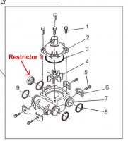
Once I have the meter assembly taken apart, I'd like to examine this restrictor just in case my rationalization is correct. However, I can't find anything called a restrictor on the exploded parts diagram. I suspect that it is the unnamed part on the diagram on page 18 of the manual that Reach4 and Akpsdvan supplied. (diagram attached)

Is this the restrictor?

Second,
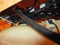
There is only a very short distance between the meter assembly and the floor above. In order to properly examine the impeller, as Akpsdvan suggested I'll need to "un hook it between the meter housing and the bypass and then undo the collar that holds the valve to the tank adapter and move the assembly forward and down". I don't have a lot of room above the meter assembly to lift it off once unhooked. I can't see this on the exploded parts diagram, but I suspect that the meter assembly has to be connected to a couple of pipes inside the resin tank so that the water can be pushed through the resin. I'm worried that there may no be enough clearance above the softener to lift the assembly off these pipes. Part number 6 on page 15 of the exploded parts diagram looks like it might be 1"-2" deep but it looks like it only has one outlet/inlet and I'd rationalize the the system would need 2. (one input, one output). Therefore, can anyone give me a better idea of how the meter assembly is connected inside the resin tank?

Thank-you in advance! You guys have been amazing with all your help!!!!!!
 

Attachments

  • valve1.jpg
    valve1.jpg
    63.3 KB · Views: 293
Last edited:

Bannerman

Well-Known Member
Messages
4,850
Reaction score
793
Points
113
Location
Ontario, Canada
The meter housing is mechanically locked (fastened) between the valve head and bypass by the 4 metal clips labeled #6. Loosening (or removing) the 4 screws labeled #5 will loosen/remove the clips. Once the clips are away from the valve/meter housing/bypass, each piece can be pulled apart by hand as the 'O' rings (#8 &#9) are what prevent water leakage.

I clearly see 2 of the clips and screws in your photo so hopefully, you have flexible plumbing pipes which will allow you to turn the resin tank to allow you to access the clips & screws on the opposite side from shown in the photo.

Once the meter housing is removed from its installed position, you will be able to turn it to examine it better from all sides which should also help you to see how to remove the meter cable.

According to the exploded diagram Noyzee posted in post #3, the part you are asking as a flow restrictor, is identified as a 'flow straightener' (part #21). That diagram shows a 'turbine' meter while your unit has a mechanical 'paddle wheel' style meter as Dittohead pointed out.
 
Last edited:

Bannerman

Well-Known Member
Messages
4,850
Reaction score
793
Points
113
Location
Ontario, Canada
Your meter cable appears to be enclosed within a stationary outer sheath. The cable commonly does not have a sheath as the twistable cable is out in the open.

The outer sheath maybe complicating the cable's removal from the meter housing and the reason for the 1"+ insertion you previously mentioned.
 

ditttohead

Water systems designer, R&D
Messages
6,091
Reaction score
456
Points
83
Location
Ontario California
No need to remove the meter from the system if you can remove the (4) screws #1 in your drawing. This will allow you to remove the meter dome. The "restrictor" is not that at all, it is a flow straightener which allows for more accurate flow readings with shorter distances. Without it the accuracy of the meter is less than it should be.

Not sure how relieving pressure would fix your systems pressure drop, sounds like you have a different problem going on, possibly bad resin. Not uncommon in mixed Anion/Cation beds, the anion resin causes precipitation issues if it is exposed to hardness ions, in a mixed bed system the hard water hits the anion bed first which typically sits on top of the cation bed, exactly backwards of how it should be.

The flow restrictor you are mentioning sounds more like a drain line flow restrictor that would limit the water to the drain. Flow restrictors for water treatment systems are commonly used but they are usually installed externally, not internally to the equipment.

Try watching the meter for a few days, does it count down or does it stay in the exact same spot? Try removing the 4 screws and checking the paddle wheel, and the body where the paddle wheel turns, let us know what you find.
 
Top
Hey, wait a minute.

This is awkward, but...

It looks like you're using an ad blocker. We get it, but (1) terrylove.com can't live without ads, and (2) ad blockers can cause issues with videos and comments. If you'd like to support the site, please allow ads.

If any particular ad is your REASON for blocking ads, please let us know. We might be able to do something about it. Thanks.
I've Disabled AdBlock    No Thanks