Prototype system

Users who are viewing this thread

ditttohead

Water systems designer, R&D
Messages
6,088
Reaction score
455
Points
83
Location
Ontario California
prototype.jpg


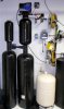
This post is intended for the people in here that have extensive field knowledge. I am building a prototype to replace my last prototype system that has worked perfectly for many years. I design and test units regularly and once my testing is complete I usually reinstall the old design into a family members house. This new design is completely over the top. I am trying to build a single valve system with 4 different medias using off the shelf, non special ordered items. Most of my previous prototypes include a lot of hand machined parts. This design will have one hidden adapter that is not yet available, but shoud be in the fall. Here is the general design:
1: Fleck 7000XTR
2: 10x22 double open tank, 1/2 cu. ft. Turbidex or equivalent.
3: 14x47 tank w/ 10% crosslink resin, 2 cubic feet
4: 24 pounds of KDF-55 in a 7x18 tank
5: Catalytic GAC, 2 cubic feet in a 12x47 tank

The diagram below shows the water flow. All of my math calculations show a minimal pressure drop for a residential application and I should be able to maintain a peak flow rate of over 15 GPM. Sevice flow will be slightly less, but the truly functional medias at higher flow rates will be the softener and GAC tanks. The KDF is limited in its service rate but it will flow over 20 GPM in this configuration. Here is the question, for a municipal water application, other than being completely ridiculous, is there any major flaws in the design that you can see? I am hoping to have a system built and installed in a coupl of weeks. I am working on an article for publication in September and this system will be a small part of it if it works. One of my biggest concerns has been the frequeency of backwashing for the KDF, but this has proven to be a non issue in my old design which also includes a similar KDF tank backwashing approximately every 10-15 days. I have 20 of those units on the feild for testing and all have worked for many years without failure of the KDF.
New unit Large Web view.jpg
 

Attachments

  • prototype.jpg
    prototype.jpg
    38.8 KB · Views: 1,029
Last edited:

Tom Sawyer

In the Trades
Messages
3,625
Reaction score
34
Points
48
Location
Maine
My concerns are that if the single valve head fails then all the units go down.
 

Mialynette2003

In the Trades
Messages
944
Reaction score
17
Points
18
Location
Ocala, Florida
The way I understand the flow is 1. Turbidex 2. Resin 3. KDF and then 4. Carbon. My question would be, don't you worry about chlorine degrading the resin? Also, Neurtripure has the same set up in a single tank design (cartridge for the KDF and carbon)without the Turbidex.
 

ditttohead

Water systems designer, R&D
Messages
6,088
Reaction score
455
Points
83
Location
Ontario California
True, this would not be an ideal design for a well application or application where water treatment is considered critical vs. a luxury item like a municipal supply. I built the majority of the system last night, but I will probably not have the time to install it for a couple of weeks. I will post a picture of the assembled system next week.
 

ditttohead

Water systems designer, R&D
Messages
6,088
Reaction score
455
Points
83
Location
Ontario California
The way I understand the flow is 1. Turbidex 2. Resin 3. KDF and then 4. Carbon. My question would be, don't you worry about chlorine degrading the resin? Also, watersystem.jpg has the same set up in a single tank design (cartridge for the KDF and carbon)without the Turbidex.

Mixed media inside the same tank do not work well, no matter what people try to tell me. We have virtually every design and mnufacturers units here in house on our test benches and they all suffer similar issues. Media contact time is critical for the medias to remove contaminants from water to desired levels. The multi level systems with and without internal dividers are a very inexpensive way to get some of the affect of each media. GAC has a rated flow of 5 GPM per square foot with a minimum bed depth of 28 inches. This translates out to a service flow rate of less than 5 GPM for a 10x54 tank with the standard carbon load of 1.5 Cu. Ft. this is more of a technical issue than the real world. Medias tendto be massively underated as anybody who does chlorine injection will state that a 1 cubic foot carbon tank will remove virtually all of the chlorine even up to 10 gpm. This is true, but the carbon is being used for much more than just chlorine removal, it is being used for the removal of dissolved organic chemicals, etc.
The KDF is also a contact time dependent media to function as it is rated. Even my 28 pound KDF tank has a technical rating of only 3 GPM. it will flow at over 20, but is it doing what it is rated to do? Of course not.

My original design has the resin last, but that creates some problems with the lack of off the shelf parts to build it. my lat prototype is shown below, the tanks used for this system used to be reaidly available, the manufacturing has since moved to India and the cost and lead times make it prohibitive.

I have substituted 10% resin to minimize the damage to the resin from Chlorine and Chloramine. I agree with you that the KDF and GAC should go first, but for this design, I had to sacrafice the order.
 

ditttohead

Water systems designer, R&D
Messages
6,088
Reaction score
455
Points
83
Location
Ontario California
Totally agree with you on this. it is more of an application and green technology design for very specific applications. We are testing some new adapters to see what can be done, more than what should be done.

Can we use a single valve and 4 tanks worth of media, can we meet a real world flow of 15 GPM while still maintaining 98% chlorine, Organics, heavy metal, hardness, and sediment above 5 micron rejection?

Our multi meida tanks with and without dividers are only acheinving 80% at higher flow rates for chlorine, 70% for organics, and 70% heavy metal reduction at that flow rate. While this is extemely good, it can be improved upon. We use this type of unit testing to see what can be done, then start scaling it back too a marketable design later. The pictures shown are huge sellers primarily becasue they are fairly inexpensive, save a lot of waste water, and are simpler than a dual valved system. These are the replacements to the ugly blue prototype I have now. Ecotwin.jpgeco.jpg
 

Tom Sawyer

In the Trades
Messages
3,625
Reaction score
34
Points
48
Location
Maine
If nothing else I have to give you a high five for creativity. The thinking man will always prevail
 

Chevy427

New Member
Messages
172
Reaction score
0
Points
0
Location
USA
I, too, like a thinking man and the wonder of initiating new designs as well as the fortitude to put it to the test. My major concern with this truly multiple-bed system is the wide variants in backwash flow rates enough to lift one media all-the-while not piston another media (carbon/resin) to the top of its respective tank. KDF, with all its wonderful attributes, doesn't do well in volumes; it is extremely heavy and tends to solidify in a short time if not completely lifted and expanded during back wash periods. I have tried lifting it in 6" tanks with 6 gpm and nothing more than a small geyser of media was elevated above the bed--the rest of the bed remained motionless.

With the footprint your design currently occupies, two separate valves would prove more efficient and practical. In your design, would the brine solution go through all four tanks?
 

ditttohead

Water systems designer, R&D
Messages
6,088
Reaction score
455
Points
83
Location
Ontario California
Excellent observations for the backwash rates of the different media. This is more of an experiment on what can be done. I have adjusted all the tank diameters to "balance" tyhe backwash rates to their manufaturers recommended levels. The only one I am slightly off on is the water softener, I am slightly higher than the recommended 5 gpm per sq. ft. level, but I am also running a slightly higher than normal freeboard.

The backwash rates are based on surafec areas.
Micro-Z/turbidex requires 15 GPM per sq. ft, thus the 10" diameter tank 6-8 gpm
Softeing resin requires 5 gpm per sq. ft, thus the 14" tank with a slightly lower resin level. 6 gpm
KDF requires a 20-25 gpm per sq. ft backwash rate, thus the 7" tank. 6-7 gpm
8x30 catalytic GAC requires a 8-10 GPM bsackwash rate, thus the 12 inch tank 6-8 gpm
I will probalby use an 8 GPM flow control allowing the KDF to have the best possible chance of backwashing effectively. KDF only expands 10% at a 25 GPM per sq ft backwash rate. Most other medias have a 20-30% expansion rate You are definetly right about KDF being a pain.

I feel KDF and Pyrolox are the 2 best modern medias available, they are also the two most difficult yo get to work right. They must be set up correctly to work as advertised and to last. The old blue system you see in the pictures above go for ten years and over 2 million gallons of water between KDF changeouts.

The system will be designed with a downflow brine so excessive dilution of the brine will not occer going through just the Micr-Z tank. We regularly build units with a full 2 cubic feet of resin prior to the resin with no noticable or caculable changes in brine efficiency. If I move the softener tank to the end of the design which would be a more proper way to build this unit, I would definetly go upflow brining. Unfortunatel, I have been unable to come up with a good way to do that. The "off the shelf" tanks are not available with the proper openings.

I really apreciate the input. It is helping me tremendously to find any bugs prior to building this unit.
 

Chevy427

New Member
Messages
172
Reaction score
0
Points
0
Location
USA
Obviously, you have a passion for details and solutions as well as getting 'outside the box'. Keep in mind that individual media service flow rates and backwashing flow rates reduces as it goes through each consecutive media prior to it AND whatever follows. I am afraid you will suffer from diminishing returns. Nothing kills media faster than not being able to 'clean' itself.

My biggest issues with KDF besides backwash flow rate is the expensive of replacement. That's why I prefer using KDF in smaller, refillable cartridges, which can be placed anywhere in the scheme of things. KDF is an excellent media but must be applied in specific ways to get its longest life and most effective results.

I am curious about the adaptor that criss-crosses the tanks. where does that come from?

Not sure of your meaning: "We regularly build units with a full 2 cubic feet of resin prior to the resin..."
 

ditttohead

Water systems designer, R&D
Messages
6,088
Reaction score
455
Points
83
Location
Ontario California
We build a unit called the Enviro-twin but it is marketed under manu names by other companies. The flow is identical to the stacked systems. The limitation of stacked systems is a height issue. By putting the tanks next to eachother, you can greatly exceed the shared valve design. The marketing is the water savings, the fact that everytime the water softener regenerates, all the waste water is "resused" to clean the carbon tank for free. The real genius is in the money savings of only having to buy a single valve. This simplifies the system, saves water, and reduces cost while increasing marketing value.

Kdf in traditional tanks can be done very easily but you are right in the expensive replacement costs. It requires a lot of waterto backwash. No less than 20 GPM per sq. ft, and preferably 25-30 to ensure many years of service. If you have enough water to backwash KDF, it can be easily used. In the past, the residential control valve, (5600, A155, Erie 541) could not backwash this media. The new generation of controls (Fleck 7000, WS1) can easily backwash it. It has opened up some exciting new markets for special applications where KDF really shines. Pre GAC treatment especially of Catalytic GAC's or applicaions where GAC should not be used IE: USP and WFI applications, GAC is avoided in engineering due to its high potential for bacterial and thus TOC problems.

The adapter is by the company I work for. If you want detailed informatiuon on it, please send me a message and I can get you detailed information. I dont want to promote the company I work for if I can avoid it. We are an OEM distributor for water treatment systems. We primarily sell to large OEM's but we do sell to dealers as well. We do not sell to end users a all.

I have really enjoyed reading through the posts on this forum, a few guys in here have an excellent knowledge of the industry that I have had a serious passion for over the past 25 years.

Lastly, the "dimnishing returns" on the backwash rates, so far my calculations show that if I add no more than a 10% buffer for the backwas rates, with these small tanks and the CV rates of each item... I should maintain the backwash rates of all the tanks while slightly exceeding the backwash rate of the softener tank. I have adjusted the freeboard of the softener tank to accomodate this, but... I have also lessened the resin quantity to increase the frequency of regenerations due to the KDF tank. I have experimented heavily with residential KDF tanks and have found that every 10-15 days, so long as you aggressively backwash it to 25 GPM per sq, ft, is ok, even though the manufacturer recommends every other day.
 

ditttohead

Water systems designer, R&D
Messages
6,088
Reaction score
455
Points
83
Location
Ontario California
prototype.jpg

Here it is, installed and operational.

Final equipment specifications:

Stage 1: 10x22 with Garnet underbedding, 1/2 cu. ft. Turbidex. Reason, to eliminate the need for pre sediment filtration on my Reverse osmosis system. Turbidex filters down to 3-5 microns, more than adequate for any standard reverse osmosis.

Stage 2: 14x47 with garnet underbedding, 2 cubic feet of softening resin, 10% crosslink. I also used a spider distributor for 14" tanks for better backwashing and distribution. I am not a fan of the spider distributors, but for this application I thought I would give them another try. I also slightly underfilled this tank since the backwash will slightly exceed the recommended 5 GPM per Sq. Ft. rating.

Stage 3: 7x13 Garnet underbedding and 30# of KDF55, reason: Removal of heavy metals, and pre treatment of the GAC bed.

Stage 4: 12x44 tank, garnet underbedding, 1.75 Cu. Ft. of CarbSorb. This GAC has been an amazing product, other than the difficulty in getting it to rinse down, this stuff is the nastiest, dirtiest carbon I have ever seen, it also works better than any we have tested.

So far, it is working great. Took me most of the day to build, install, rinse down, program, and clean up my mess. It looks a little odd, but so far it is working great. I am getting over 15 GPM through the tanks with 10 PSI pressure drop. I will play with this for a few days to see if it works as well as my calculations said it would. I will be putting a rotometer on the drain line to monitor it to confirm I am consistently getting 7 GPM to the drain.

Ok, so who wants to order one? :)
 
Last edited:

ditttohead

Water systems designer, R&D
Messages
6,088
Reaction score
455
Points
83
Location
Ontario California
I have had a few odd problems with this system, Intermittent low flow as low as 5 GPM. It was mainly apparent while using a garden hose that is fed with soft water. I also had a drain line issue, the rotometer was showing a mximum flow after a minute of backwash to be 4 GPM and the system has a 7 GPM button. I figured I had a bad bottom screen somewhere in the system, and my first guess was the test screen I installed inside the softener tank. I decided on using the Heavy Fleck bottom screen on everything except the 14" softener tank. I used a test screen, a Spider distributor. That turned out to be my mistake. It had a small crack in it that was allowing resin to go between manifolds and get jammed in the top/bottom screens of the KDF and the Turbidex systems during service and backwash. I tore the system down, replaced the spider distributor (cracked lateral) with the 40922 screen, cleaned out the screens in the remaining systems, and retested, the system now works perfectly again. Ok, so my personal recommendation, the Spider distributor is extremely expensive, and should not be used. The installation requires the laterals be kinked together to fit through the opening, this is probably what caused the damage to the lateral. There is no other way to install the lateral, so a standard high quality bottom screen, and a gravel bed is the right way to do it. I would avoid the Spider distributor.
 

LLigetfa

DIYer, not in the trades
Messages
7,493
Reaction score
574
Points
113
Location
NW Ontario, Canada
I know you stated that this thread is for "people in here that have extensive field knowledge" and I am far from fitting that description but humor me if you will cuz I want to understand. Why would not the underbedding have kept the resin out of the bottom screen?
 

ditttohead

Water systems designer, R&D
Messages
6,088
Reaction score
455
Points
83
Location
Ontario California
I know you stated that this thread is for "people in here that have extensive field knowledge" and I am far from fitting that description but humor me if you will cuz I want to understand. Why would not the underbedding have kept the resin out of the bottom screen?

Perfect question. The spider distributor cracked right at the top, and the underbedding was loaded to just barely cover the screen. When it cracked, it sucked in some garnet, and resin. I used the large spider distributor which is over 7" tall, plus the fact that it sits high in the bottom dome, it sits almost 9" hig, almost triple the height of a standard bottom screen. I designed the system to handle only 2 Cu. ft. of resin so I thought the additional height of the spider distributor would be fine especially since I was planning on a higher backwash rate than normal.

The spider distributor is a great concept, but the percieved benefit and potential problems, and the extreme price make it difficult to recommend in a downflow system.
 

ditttohead

Water systems designer, R&D
Messages
6,088
Reaction score
455
Points
83
Location
Ontario California
I finally fixed the picture, the final design has been working since January without a problem. I added in waste diversion based on TDS. The RO waste shares the same drain line which goes to irigation as well. I replaced my waste TDS monitor with a digital unit from HM Digital, and I added a 2 Cu. Ft. Post RO DI tank for my carwash and test sink. I have also added some more pressure gauges to see if there is any loss of flow through the system, so far, it is flawless. Obviously this is not exactly a marketable system but it does prove a few design ideas. It has no noticeable loss of flow through the medias with flow rates in excess of 15 PSI, and the backwash rate sharing through the different sized tanks works great with no loss of flow. The salt dilution is no issue condidering it only goes through an additional 10x22 tank prior to entering the softener tank.
All in all, I like the design, and the water it produces is great.
 

ByteMe

Semi-Pure awesomeness!
Messages
174
Reaction score
12
Points
18
Location
Scio Ohio
Hey Dittohead,

You are doing what I have been thinking. I just moved into a rental, after I build a custom house (less than a year away) I want a water filtration system much like this. Would you be interested in helping/sharing with me to design such a system. I do not know yet what my water will be like (well/city,etc). I have just recently become interested in water filtration technology, so I am way behind your knowledge, but I love this topic from an engineering perspective.

Feel free to post different systems/pictures of experimental systems you are involved with. Makes very interesting reading/learning.

FYI; I am a corrosion engineer for a super major oil company.
 
Top
Hey, wait a minute.

This is awkward, but...

It looks like you're using an ad blocker. We get it, but (1) terrylove.com can't live without ads, and (2) ad blockers can cause issues with videos and comments. If you'd like to support the site, please allow ads.

If any particular ad is your REASON for blocking ads, please let us know. We might be able to do something about it. Thanks.
I've Disabled AdBlock    No Thanks